

Television game prototype from Czechoslovak Tesla VÚST
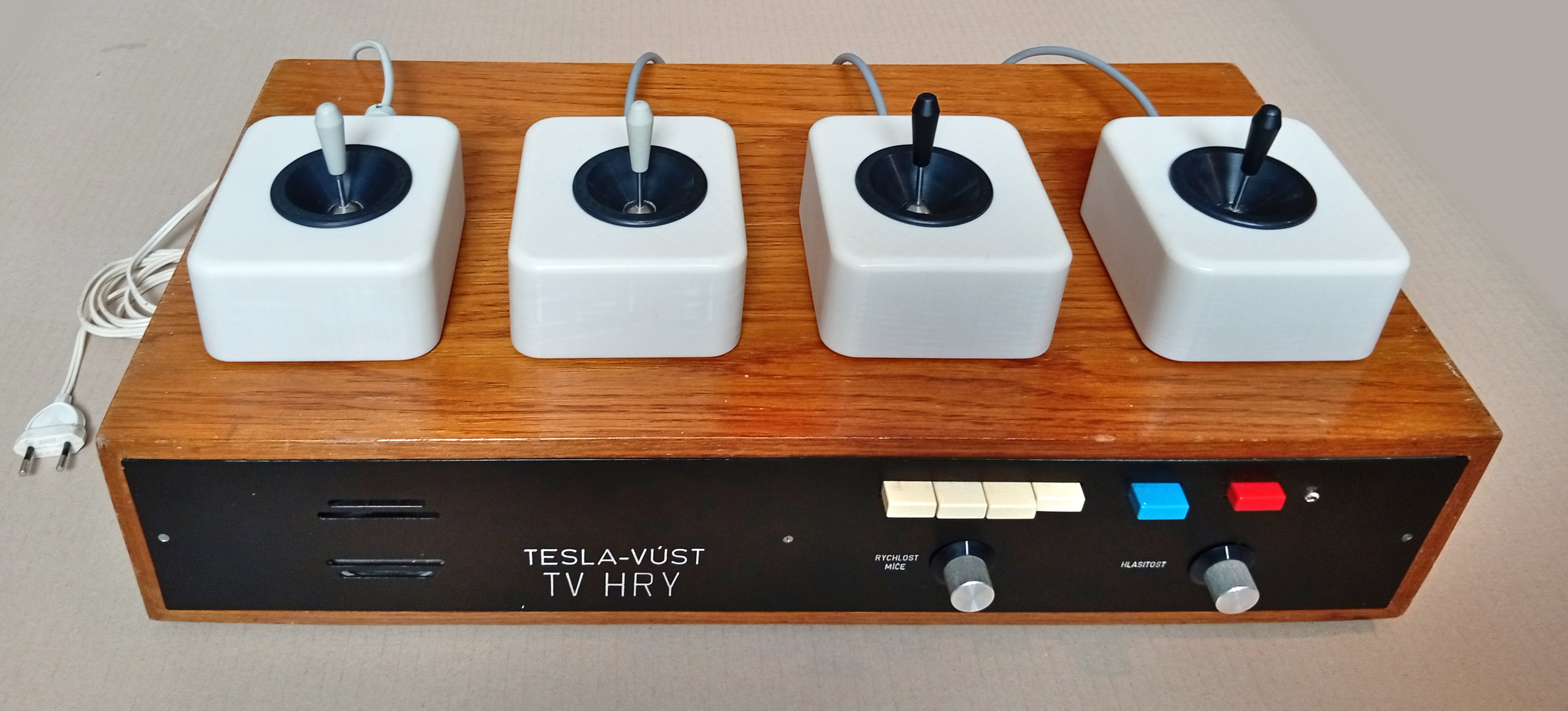
In 1977, Czechoslovakia saw the arrival of an exciting novelty - the so-called Television games. The magazine Amatérské radio published two separate construction guides for such devices (in issues B1+B6/1977 and A10+A11/1977), which had been entered into the AR-TESLA Competition as early as September 1976. In May 1977, the first prototypes created by various departments of the national enterprise TESLA also appeared at the Brno trade fair and at the Prague exhibition Dny nové techniky (New Technology Days): a simple TV tennis (Tesla Piešťany), based on the Amatérské radio guide and developed in cooperation with the Prague Hi-Fi club (later manufactured as the XD 8000), an equally simple TV volleyball (Tesla VÚST) built from transistors only, and finally the "TV HRY" ("TV Games") device (also Tesla VÚST), which is the focus of this article.
It was unquestionably the most advanced domestic game of its time, and its sophisticated design confirms the top-class level of what was then the A. S. Popov Research Institute for Communication Technology (VÚST). We are talking about the so-called first generation of video games, characterized by hardwired logic without a microprocessor (although the definition is not entirely clear-cut), which can be further divided into early devices built from discrete components or basic integrated circuits only, and more advanced versions using dedicated game chips. The TV HRY prototype sits somewhere on the border between the two groups. It was created within months of the arrival of the globally groundbreaking AY-3-8500 chip, technically it still belongs to the first group, but with four games and an on-screen score, its functionality rivals the second. This sets it apart from other domestic games of its era and places it in the company of larger projects that were fairly rare even worldwide, such as the various (by then already dying out) clones of the original arcade PONG in the West, or some (conversely, later) Soviet projects in the East, led by the Palestra 02 console (1978). The VÚST prototype was, however, also quite complicated and expensive for its time, so it remained just a prototype and a one-off exhibition attraction, leaving only very brief traces in the period press - a few photographs, and a short remark about the economic unviability of a device built from about 80 integrated circuits (AR B6/1977). After its successful exhibition premiere, it quickly vanished from the scene and became something of a mysterious chapter among domestic games, one about which little was known.
Even today, not all questions have been answered (for example, we don't know who designed this game), but we can examine the device itself, which has fortunately survived to this day and, on the initiative of the Herní historie (Game History) association, has been thoroughly documented and repaired. It must have been made between September 1976 and May 1977 (based on the latest date codes on its components and period reports of the finished device's public presentation), which makes it quite likely the oldest surviving domestic video game of all. Even in the context of the Comecon countries, it is probably among the oldest projects of its kind.
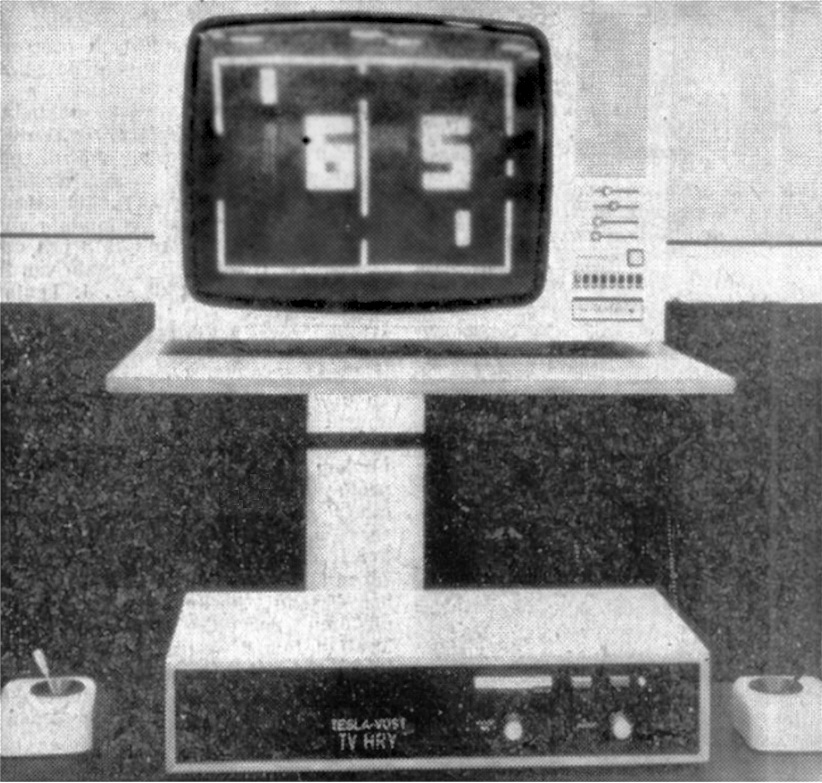
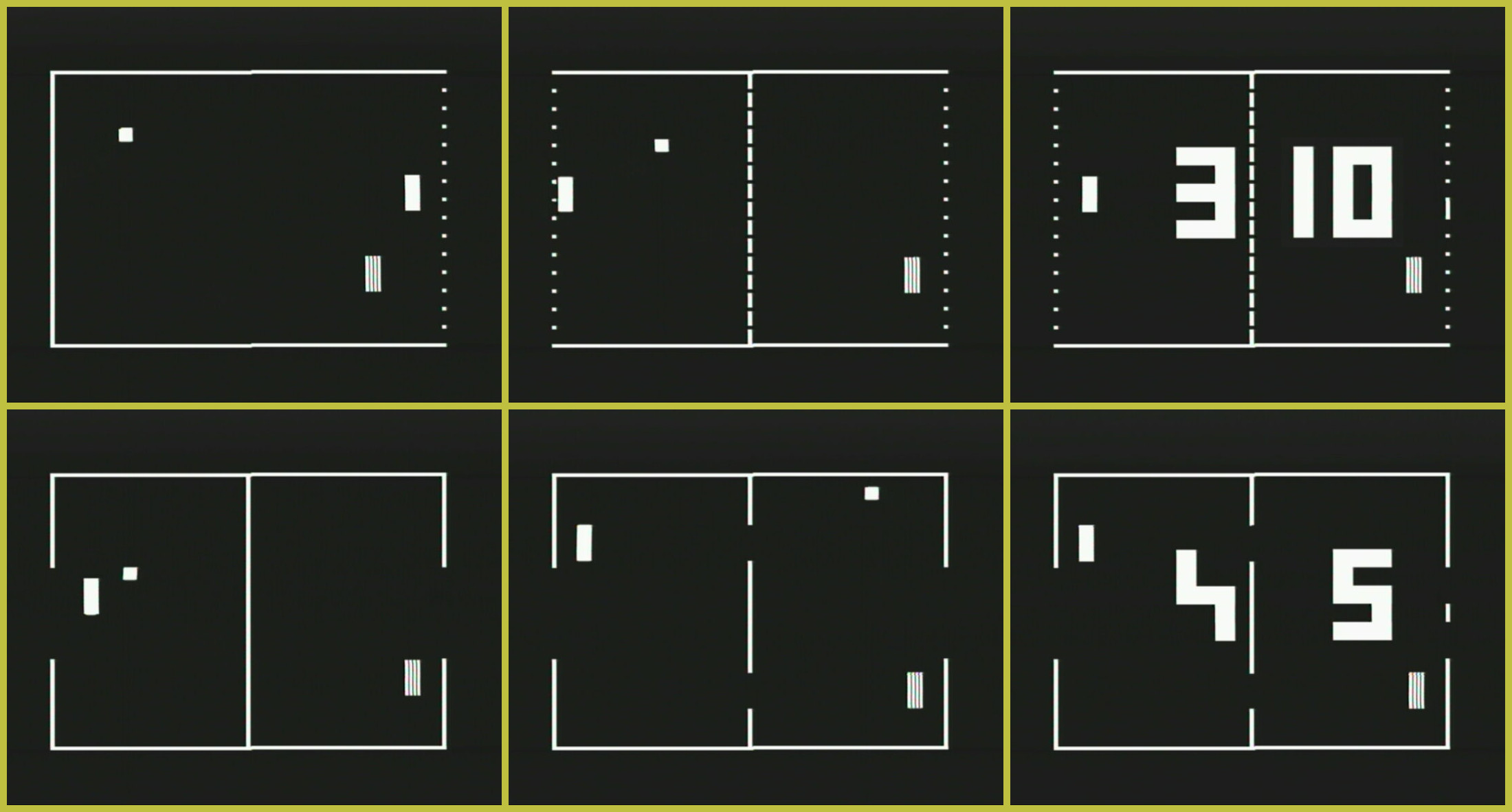
Which games we can play is probably best shown by the picture - as was usual at the time, these are simple ball games. There is classic tennis and hockey (with goal openings in the side walls), as well as pelota played against a wall, which in this version is a game for two (with both/all paddles on the same side of the field), though it can also be played solo. A particularly unusual one is basketball, played on the same field as hockey, in which the players control not only their paddles but also the openings in a barrier in the middle of the field (a possible inspiration may have been the "hole-in-the-net" game from Elektor magazine 5/1976). The game supports a generous number of up to 4 players split into two teams, with comfortable paddle control using analog joysticks. There are settings for the ball speed and the volume of the sound effects (which signal ball bounces and goals), and a score display of up to 19 points, which goes dark when the ball enters the field and can be reset with a button.
At first glance it is clear that this is an original design that doesn't copy any existing game. There are elements specific to Czechoslovak designs, such as the score digits going dark when the ball enters the field and serving a new ball by backing the paddle onto the boundary line, but also completely original features found nowhere else: goals indicated by a dot displayed in the respective goal, which also serves as a prompt to serve a new ball, unusual dotted rendering of the lines on the field, or penalty points for crossing the center line with a paddle in tennis and basketball. On the other hand, ball bounces take only the simplest form in this game - the angle is always the same and cannot be changed by maneuvering the paddle or in any other way. This apparent drawback is, however, offset by the comfortable movement of the paddles in all directions, which makes it possible to change the ball's trajectory at any point. The designer also paid considerable attention to clear and simple operation (perhaps with exhibition use directly in mind). Besides the dots indicating goals and the really large score digits, this is also evidenced by the visual distinction between the paddles: the left team controls white paddles using equally white joystick levers, while the right team has striped paddles and dark levers, and the joystick boxes placed on either side of the device are even mirror-symmetric - a remarkably refined design in the context of Czechoslovakia in 1977. The controls are also simplified to the maximum - serving happens simply by touching the boundary line with the paddle, and after the maximum of 19 points is reached, the game restarts on its own after a few seconds. So, visitors to the exhibition didn't have to press any buttons at all, it was enough to simply grab a joystick.
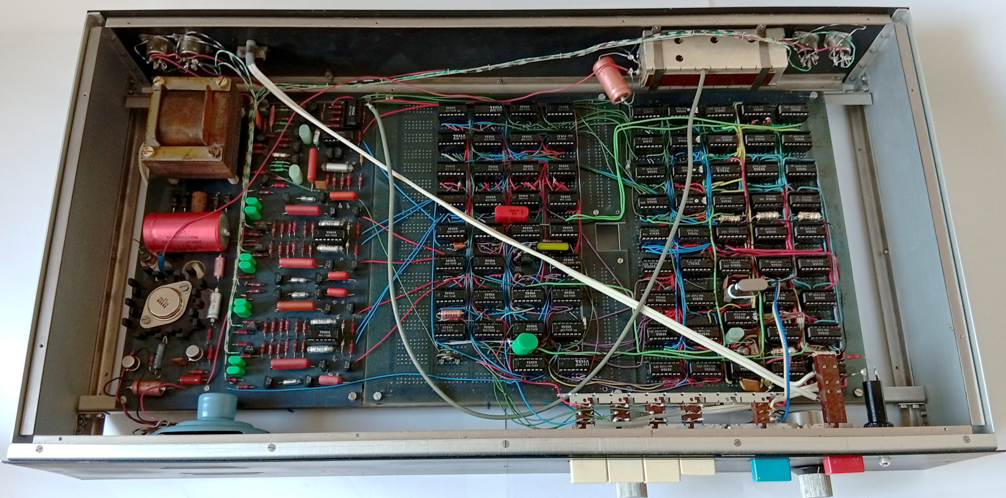
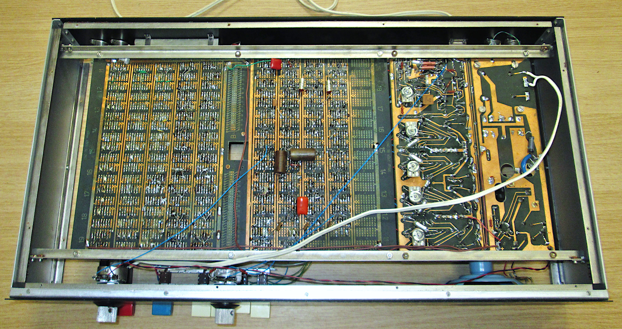
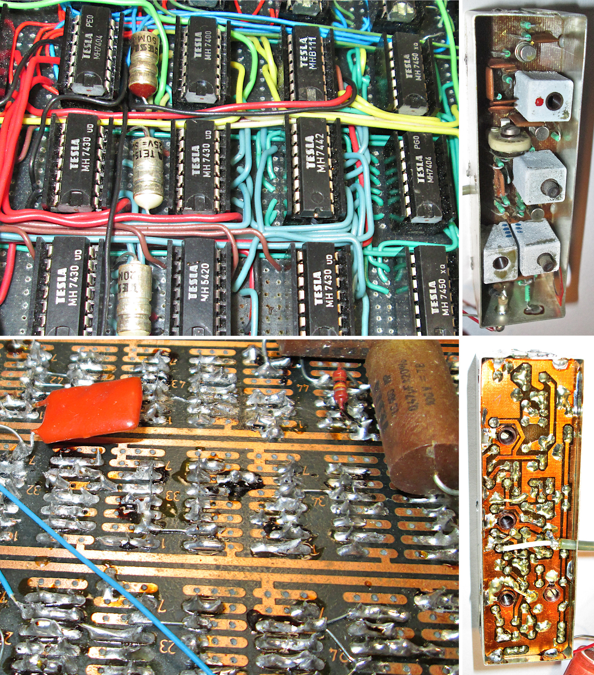
Let's now take a look inside the device. After loosening two screws on the back, we can slide a precisely made metal box out of the elegant wooden case (560x290x122mm including feet), and after unscrewing its top and bottom covers, both sides of the electronics boards are nicely exposed. At first glance it is obvious that this is a prototype. While the power supply and the analog section have a regular printed circuit board, albeit with a few later-done modifications, the entire digital section with dozens of integrated circuits is built on a pair of universal prototyping boards (made directly at VÚST). In places we also encounter the old marking system from the early days of domestic production of these components - for example MJA111 (which is MH7472) or the somewhat misleading MHB111 (MH7410). The integrated circuits sit in quality gold-plated sockets and are interconnected by a precisely executed, yet very confusing flood of wires. A metal box attached to the rear wall houses the RF output modulator for the TV set, which bears the clear signature of VÚST as the country's leading communication technology institute of the time - compared to other games of the era, it is unusually complex (3 transistors, 4 tuned circuits) and precisely built, and the use of a BNC connector on the output isn't exactly amateurish either. If we want to judge the device in the style of the time, by the number of semiconductor components used, we count 82 integrated circuits, 40 transistors and 13 diodes.
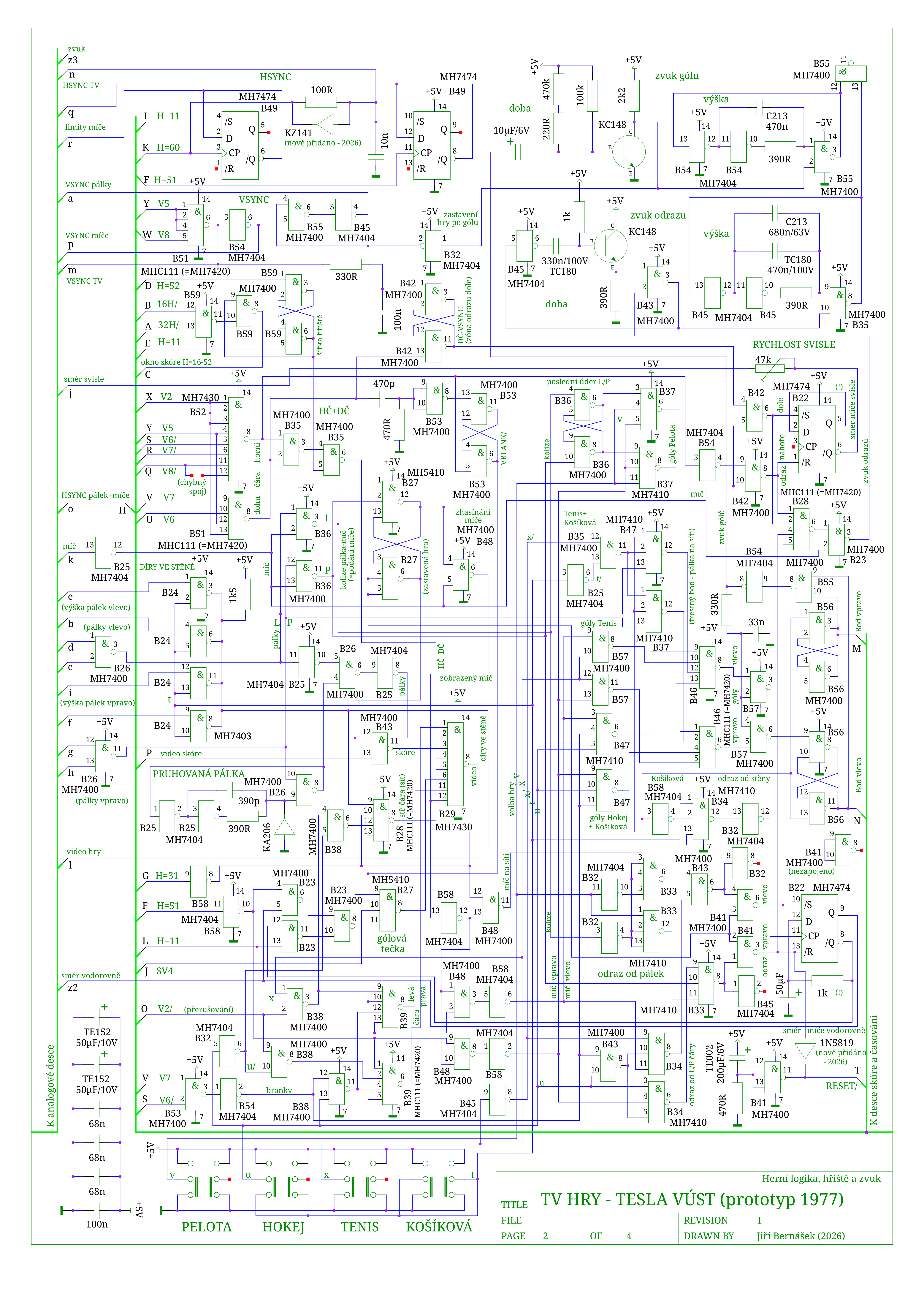
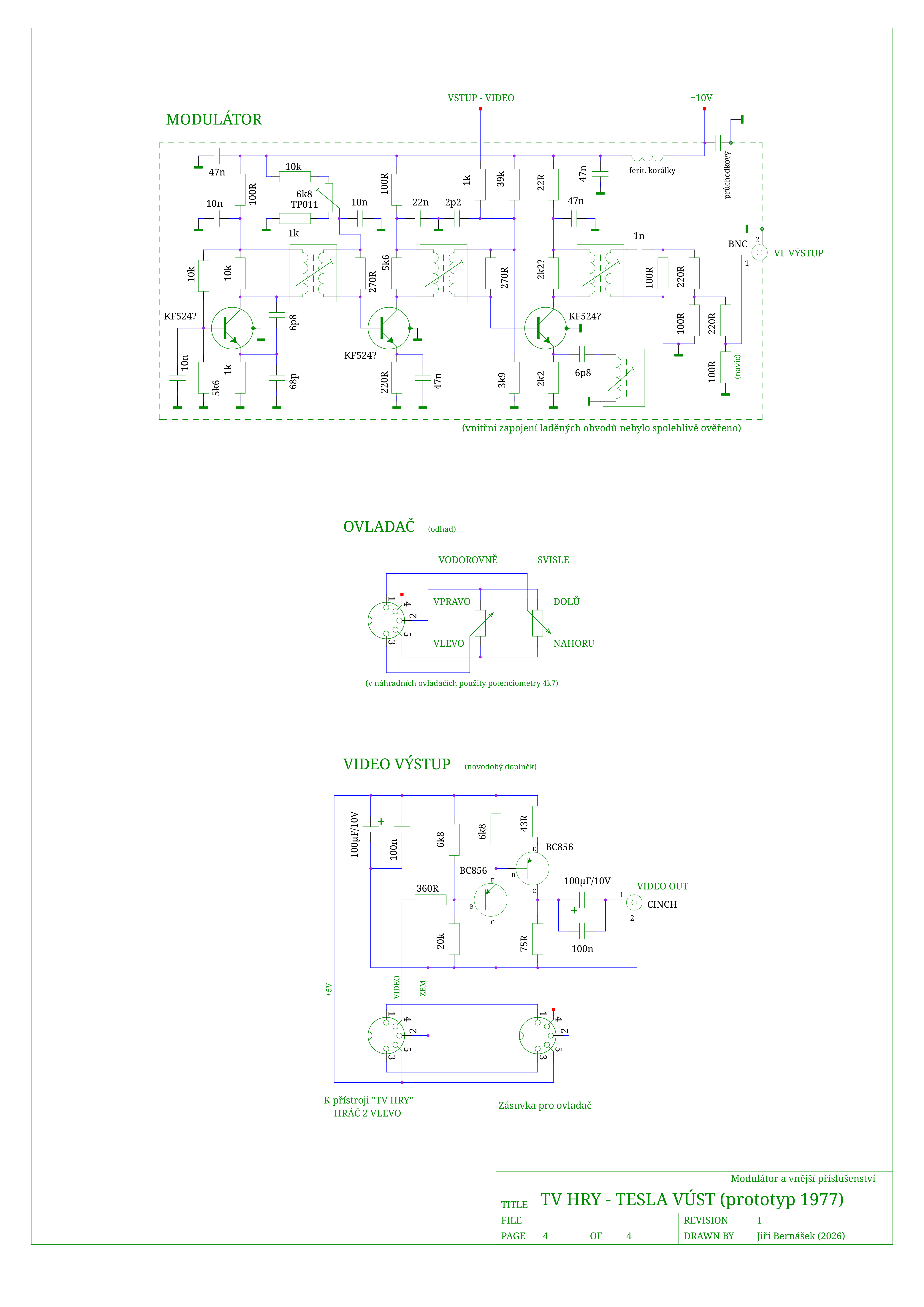
Although it appears the original documentation hasn't survived, careful examination of the aforementioned "wire hell" eventually yielded a newly drawn schematic of the whole device, which you can see in the pictures. (The digital boards are labeled with the letters A and B to tell them apart, and the integrated circuits on them keep their original position numbers as marked on the back of the board. For the purposes of this documentation, the wires connecting the boards were labeled with lowercase and uppercase letters of the alphabet.) Above all, we can notice that unlike comparable Western counterparts (PONG clones or the AY-3-8500), this game isn't fully digital, but is essentially an analog game (in terms of generating the moving game objects), supplemented by an extensive digital section. (The MAS601-603 chips and some projects from the Soviet Union work in a similar way - more on that in another article.)
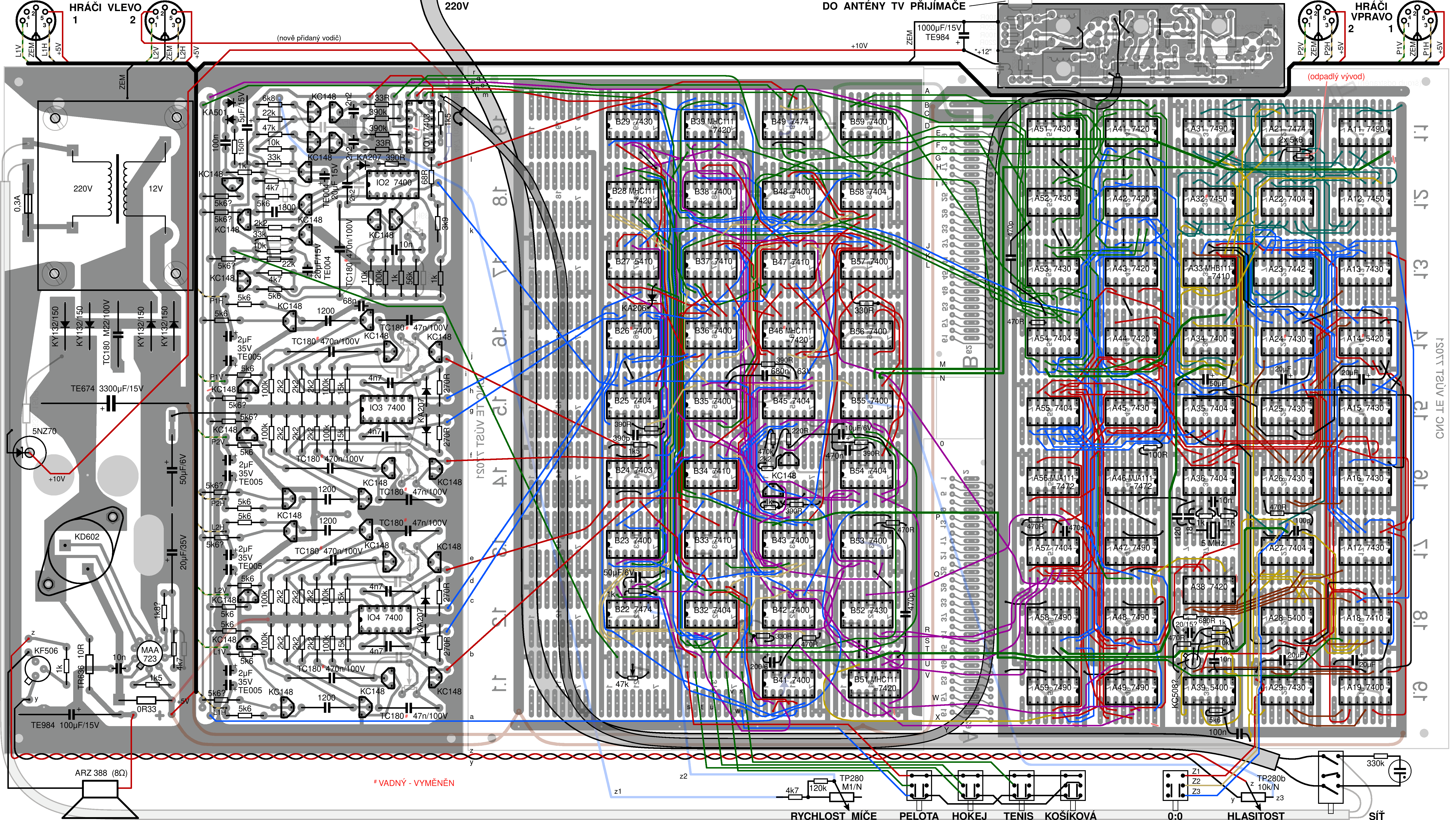
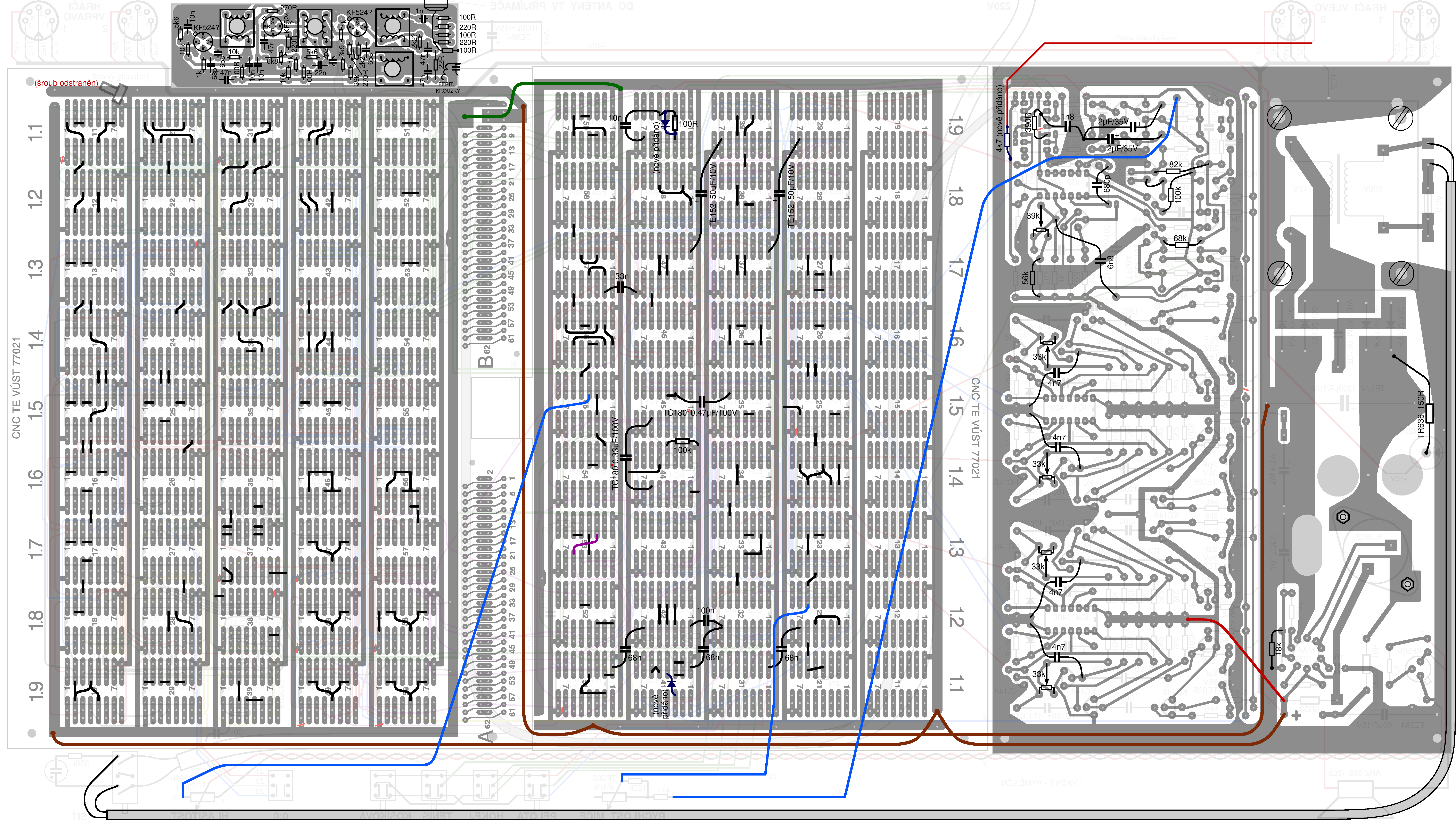
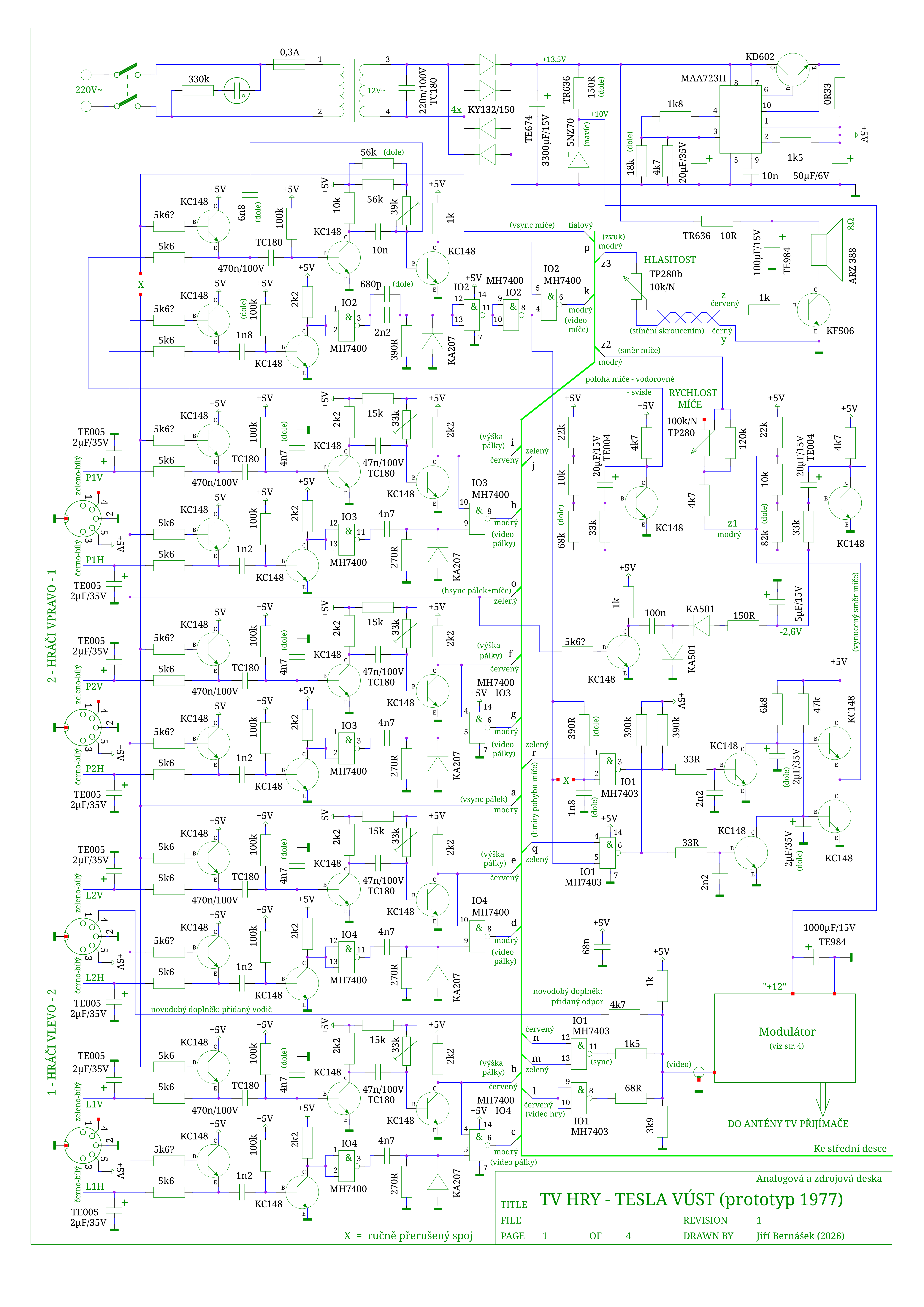
The first page of the schematic (corresponding to the left of the three boards in the device) contains, besides a robust power supply and other minor parts, mainly the analog section. Five practically identical circuits generate the images of the four paddles and the ball. They use the classic principle that carried over from the first console, the Magnavox Odyssey (1972), through the Western European magazine Elektor, which was the usual source for domestic designs, all the way to the guides printed in Amatérské radio and adopted in the Tesla XD 8000 consoles. Even in VÚST's version, the circuit doesn't differ significantly, but it does include some improvements: the sync pulses are fed through transistors instead of the usual diodes, which elegantly solves the otherwise typical problems with overloading of the sync signals, and the ball movement has improved linearity thanks to replacing the usual RC networks with at least simple integrators. To drive them, the circuit generates an auxiliary negative voltage (-2.6V), and there is also a very unusual circuit (a simple regulator) the task of which is to keep the ball at the edge of the field based on digitally generated limits, should it tend to fly away horizontally - this mainly determines the spot where a new ball can be served after a goal. The number of players is selected simply by disconnecting some of the controllers, which moves the respective paddles (in an analog way) off-screen, where they aren't displayed at all. The fourth page of the schematic, documenting the inside of the RF modulator and the external accessories (mainly the controllers), essentially also belongs to the analog section.
The sync pulses in this game are generated digitally (in the sense of counting clock pulses), which we find on the third page of the schematic (or on the right board in the device). The clock generator (at the top of the page) is built in a very unusual way. It is based on a 5MHz crystal (one of the few types available at the time), which, after its frequency is divided by two and by five, determines the time step in the horizontal direction of the picture in an unusual rhythm of 1.6:0.4μs (in the rest of the text, I nevertheless assume an average step of 1μs). Next come the counters for 64 steps per scan line (64μs) and 625 half-lines per frame (20ms). They are built from unusually wired MH7490 chips, where the separate "A" sections of all five chips (A47-49 + A58-59) form the horizontal (binary) counter, while the remaining three-bit sections of four of the chips form the vertical counter - which counts halves (!) of scan lines and works in a somewhat confusing and atypical base-5 number system (the sections of the MH7490 chips used here are actually modulo 5 counters; I labeled the counter outputs 1H-32H and V1-V8). This arrangement tempts one to speculate that the MH7490 was much more common than the MH7493 at the time, but the more likely explanation is an effort to follow standard video timing truly precisely: a four-stage modulo 5 counter overflows after 5^4 = 625 half-lines, achieving correct picture timing with the counter alone, without any additional logic. The result is perhaps even too precise - this game is a rare example of a first-generation console that produces a full (interlaced) 625-line picture (though of course only black-and-white and without sound; a similar arrangement can perhaps only be seen in some later projects from the Soviet Union). Given what is displayed, however, this isn't necessary at all, and because the vertical counter steps in a half-line rhythm, it also leads to unpleasant effects in the form of the right half of the picture being shifted up by 1 (interlaced) line (see the boundary lines of the field in the screenshots). This counter arrangement also causes the atypical dotted rendering of some lines on the field, resulting from the fact that the signals of the individual binary digits of a "modulo 5" counter never have a 1:1 duty cycle. The same property of the aforementioned initial divide-by-five stage also makes it possible to display vertical lines much thinner than the otherwise used 1μs time step would allow, and the considerable size of the score digits is probably related to it as well, since there it is conversely desirable to avoid such asymmetry in pixel dimensions. In the lower part (of page 3 of the schematic), several timing signals are decoded from the counter outputs, which mainly determine the layout of the picture and the field - this is drawn in more detail in the picture (the units are 1μs and 1 scan line within a field).
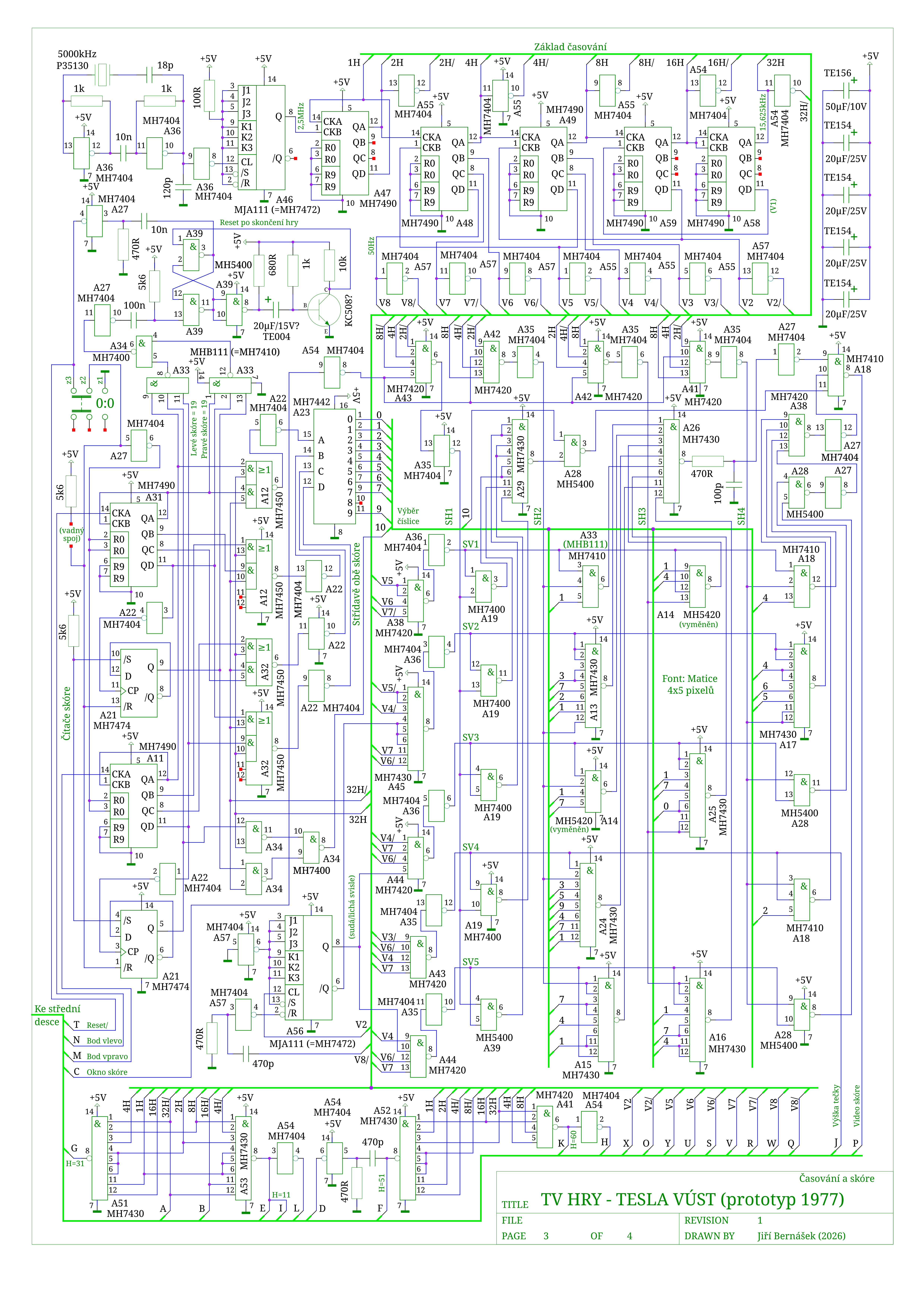
The largest part of the third page of the schematic is taken up by the score circuits. On the left, we have a pair of 4+1 bit BCD counters for the scores of both players (A11+21+31), which can be reset in three ways: with a button, by the "T" signal generated when the device is switched on, and by time-delayed detection of the final state of 19 points. Next comes a multiplexer that selects between the two scores according to the half of the picture currently being drawn (A12+32+34), followed by the digit display circuits, done in a sort of Czechoslovak style: while foreign games in both the West and the East usually used the 7448 chip intended for seven-segment displays to obtain a font, or (somewhat illogically) its equivalent built from discrete logic, domestic designs, given the unavailability of the 7448, skip this unnecessary intermediate step entirely and work directly with a bitmap font. In the case of VÚST, the schematic contains a 4x5 matrix of logic gates (two of which are omitted), which decide whether individual pixels light up in a 1x5 or 3x5 grid for the digits "1" and "0-9", based on the horizontal and vertical raster signals (I labeled them SH1-4 and SV1-5) and the digit currently being displayed. The principle is thus the same as in the second variant of the circuit printed at the same time in Amatérské radio B6/1977, but the implementation differs (in the number and shape of the digits).
The core of the game is located on the middle board, which corresponds to the second page of the schematic. Here, the digital timing is used to generate the picture sync (the vertical sync pulses are simplified in the way that was common at the time - without serrations) as well as trigger pulses for generating the paddles and the ball. The field with its lines and the optional dot indicating a goal is also generated here, and the paddle, ball and score signals are added, so that the complete video content comes out at output B29. Collisions are detected as well, according to which the ball direction flip-flops (B22) are toggled, or goals are registered. It is worth noting that in pelota, any player can hit the ball (they don't necessarily have to take turns), but in the case of a goal, the point goes to whoever last successfully played the ball (which is remembered by the flip-flop on B36). The circuits for the individual functions (field display, ball bounces, goals for the individual games) are mostly separate and share only a few common gates. There are also sound effect circuits and a power-on reset generator (a fairly unusual feature in this generation of video games).
The goal logic, with stopping the game and serving the ball, deserves a closer look. Detection of a goal by the ball colliding with the goal line (or, in some games, a penalty point for a paddle crossing the center line) activates one of the R-S flip-flops built on chip B56, whose outputs control the score counters via wires M+N. A goal registered this way blocks, via the output of gate B55-8, the detection of further (duplicate) goals caused by the ball moving while the game is interrupted (or possibly another penalty point when the paddle returns to its correct half of the field), and at the same time triggers the goal sound effect via a transistor (near the top edge of the schematic). For the duration of this sound, the paddles are not displayed (they don't receive trigger pulses from the output of gate B55-6), and the flip-flop built on chip B27 switches to the stopped-game state. This suppresses the display of the ball and the sounds of its bounces, and activates the display of the score and the goal indicator dot instead. While the game is stopped, the ball is therefore invisible and doesn't bounce off anything on the left or right, but it keeps moving up and down along the boundary line, where it is held by the analog regulator circuit. Once the sound effect ends, the paddles are displayed again and can then catch the (invisible) ball on the boundary line and bounce it back into the field. This serves a new ball, which usually flies out from one of the edges of the paddle - it essentially finds such a spot on its own. Hitting the ball (a collision with a paddle) resets the stopped-game flip-flop, which turns off the score and the goal dot, the ball appears, and the game can continue. The goal flip-flops on chip B56, however, are only reset once the ball reaches the center line, so no further goal can be counted as the ball enters the field (the designs from Amatérské radio B6/1977 and the MAS601 chip work in the same way).
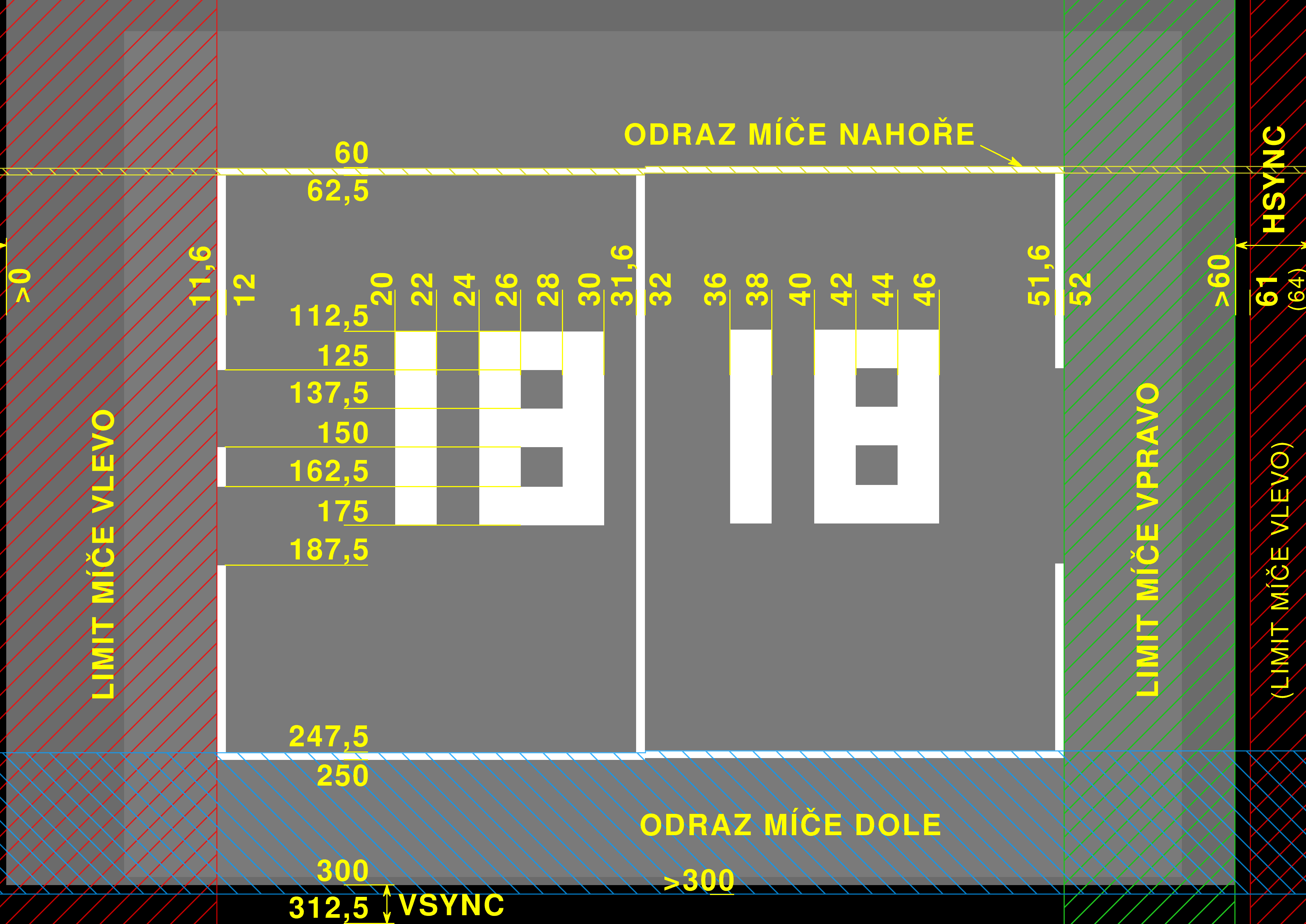
Combined with the free movement of the paddles across the whole field, however, this arrangement also has its weaknesses. Perhaps the most noticeable are cases where the ball flies along the boundary line (as it does before a serve), yet is visible. These are various possible situations in which the ball never reached the center line between the serve and a new goal, so the blocking of duplicate goals hasn't ended yet and the goal seemingly "doesn't accept" the ball. This is usually related to the ball being returned immediately by a paddle located in the opponent's half of the field, including the possibility of serving on the opponent's behalf (and thus seemingly into a wall), but the cause can also be an excessively fast ball (which takes such a large step between individual frames that it skips contact with the center line; the vast majority of games of the era have the same weakness in their collision detection). In these situations, the device is also blind to paddles crossing the center line (which applies to tennis and basketball). The second common problem is the goal (and the serving process) being indicated on the opposite side of the field from where the goal actually happened. The cause here is simultaneous detection of a goal and a ball bounce (given the ball's relatively large size), most often when we hit the top "post", i.e. the edge of the goal, in hockey or basketball, or when a paddle waits for the ball exactly on the goal line. In that case, the goal is correctly counted and the ball disappears, but it is already flying towards the opponent at the same time, so it takes up its starting position (including the indicator dot) on their side. With particularly slow movement, an unintended serve can even happen in the middle of the field, if the invisible ball meets a paddle there.
Apparently related to the above is an additional wiring change found in the device, thanks to which left/right ball bounces are suppressed immediately during the goal sound effect (by two gates of B41, next to which, however, the board also contains plain inverters with disconnected, but previously soldered outputs). This change solves the problem of a simultaneous goal and bounce at least in some cases (the bottom edge of the goal, the top or left edge of the paddle), where, due to the direction in which the picture is drawn, the goal detection does arrive a hair earlier, but the paddle, because of the way the flip-flop on B27 is wired, can undesirably delay the stopping of the game (and thus the regular suppression of the ball).
Given that this is a prototype, the presence of additional modifications is hardly surprising. They include added stabilization of the supply voltage for the output modulator and a reduction of its output signal level with additional resistors, an adjustment of the timing (edges) in paddle generation, changes to the size and speed of the ball, and adjustments of the time constants of the regulator circuit for its edge position. Two small wiring mistakes were also found (for example, some inputs of B52 are connected one pin off), as well as a few unclean solutions (pin 12 of B22 doesn't receive a proper logic zero, wire T shorts two TTL outputs together), but given the size of the device, these are just negligible nitpicks which fortunately have no effect on its function.
Looking at the schematic, we can also notice that the statement about a "not entirely digital" game applies to much more than just generating the paddles and the ball. I counted another 20 places in the device where various time intervals are measured not by counting clock pulses, but by charging capacitors - these include all of the sound generation, the paddle striping, and various signal delays that ensure the signals are properly aligned in time. Essentially, it can be said that only the basic picture layout, the field and the score are generated in a purely digital way. Nothing more.
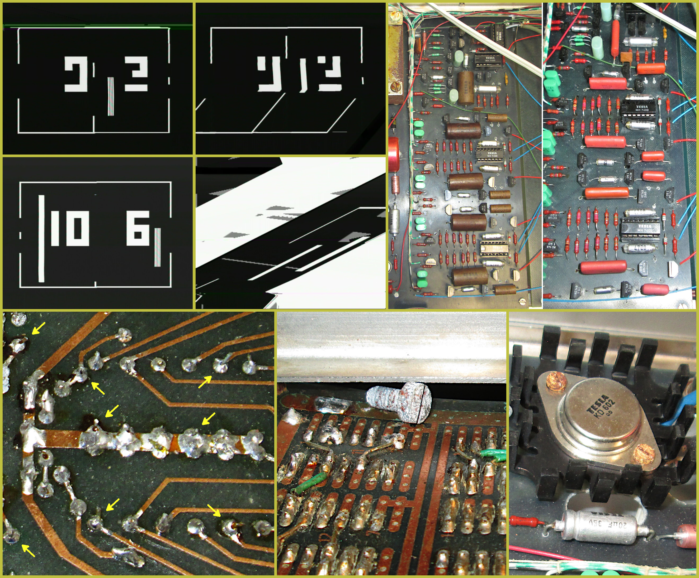
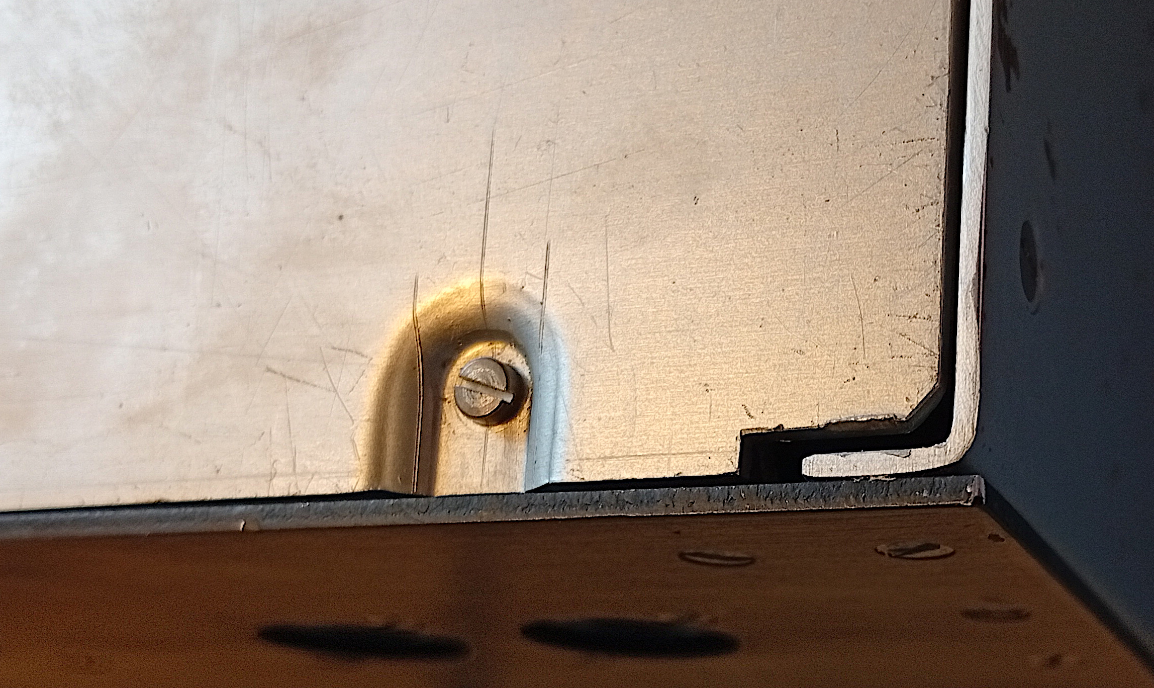
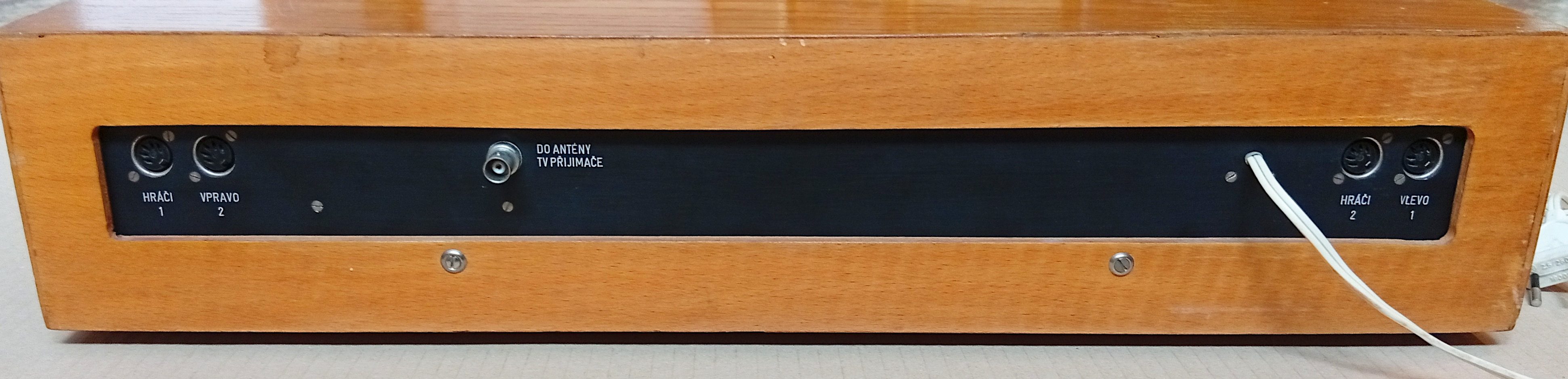
Let's also take a look at how the VÚST game device has withstood the ravages of time - after all, not long after this article is published, it will celebrate its 50th birthday. As you can see in the illustrative collage from its repair, things weren't exactly rosy. Rusty screws, some of which even snapped off when opening the cover, loose mounting of the controls as well as larger assemblies, where the screws used (M2) had been undersized from the very beginning, a broken-off output connector, only one of the four paddles on screen (and disproportionately long at that), no ball, unstable picture sync, scattered pixels in an incorrectly counted score, some bounces and penalty points not working, the ball bounce sound stretched into an annoying honk... It was necessary to replace 5 faulty integrated circuits and 11 degraded paper capacitors of the infamous TC180 type (which certainly didn't earn its popular, rather unflattering nickname by chance). Since Tesla's range of film capacitors was poor at the time, finding a period-appropriate replacement meant reaching into the "Comecon component base" (as it was called back then): the device already came with two Hungarian capacitors (Remix C213), and now Bulgarian ones (MPT-Pr96) were added as well. The biggest problem, however, turned out to be a large number of bad solder joints - in Czech colloquially, 'coldies' or cold joints. VÚST did top-class work for its time in designing the game and making the case, the printed circuit boards, and the black anodized panel with engraved lettering (they were probably even using CNC machines back then already), and the artistry of connecting all those wires deserves high marks as well. Unfortunately, the routine soldering during mass assembly of the passive components, and especially the integrated circuit sockets, is a much worse example of the standards of the time - components with poorly solderable leads and only average efforts to deal with them properly. A light tap on the device was enough to dramatically change the state of the whole game. Even back when the game was still serving its purpose, someone tried to solve this in a peculiar way - by brutally bending the board with an M4 screw jammed under its edge. It's hard to say whether this was an improvised rescue during one of the exhibitions, or whether it happened only during the game's "afterlife" (once its original role was over, one of the institute's employees took it home, thereby actually saving it for us). To make the game work reliably again (even without the screw under the board), all the cold joints had to be resoldered. Outright bad joints numbered more than ten, and the subsequent preventive resoldering of other untrustworthy points during a thorough inspection ran into the hundreds. That's not exactly a good testament to 1970s Tesla.
As part of the repair, several interventions were also needed to make the game playable today at all. A video output was added using a single piece of wire and a detachable external box (since old TVs with an RF input are becoming rare), one added diode brought the sync pulses somewhat closer to the standard length, and another ensured reliable startup of the device after power-on (here the VÚST designer took a bit of a gamble, as the startup of the game depended on the undefined initial state of one of the flip-flops - apparently the MH7474 chip was on their side back then, but unfortunately that changed over half a century...) Last but not least, replicas of the controllers had to be built from scratch based on just a few old photos, since we don't have the original ones and they most likely haven't survived.
But as they say - all's well that ends well. The game is back in proper shape, and you might come across it at RetroHerna and Czechoslovak Game Archive events. Although it is just a single prototype which, given its scale and cost, probably really never had a chance at mass production, it is nevertheless an interesting example of what a luxurious, advanced Czechoslovak video game could have looked like at the very beginnings. In this respect, it is actually a kind of counterpart to the Tesla XD 8000 game, which was simplified "to the bone", and whose prototype was being exhibited at the same time.
Sources:
- Dorian Hanuš: Otazníky nad televizory jarního Brna (ČS Televize weekly 24/1977)
- Josef Horázný: Elektronika z lázeňského města (Nová Svoboda, 3 June 1977, p. 4)
- O. Šmejkal: Dny nové techniky Tesla-VÚST '77 (VTM 13/1977, p. 394)
- Hry na televizní obrazovce (Amatérské Radio B6/1977, p. 222)
- TV tennis extensions, part 3 (Elektor 5/1976, p. 544)