

The Tesla XD-8001 television game under the microscope
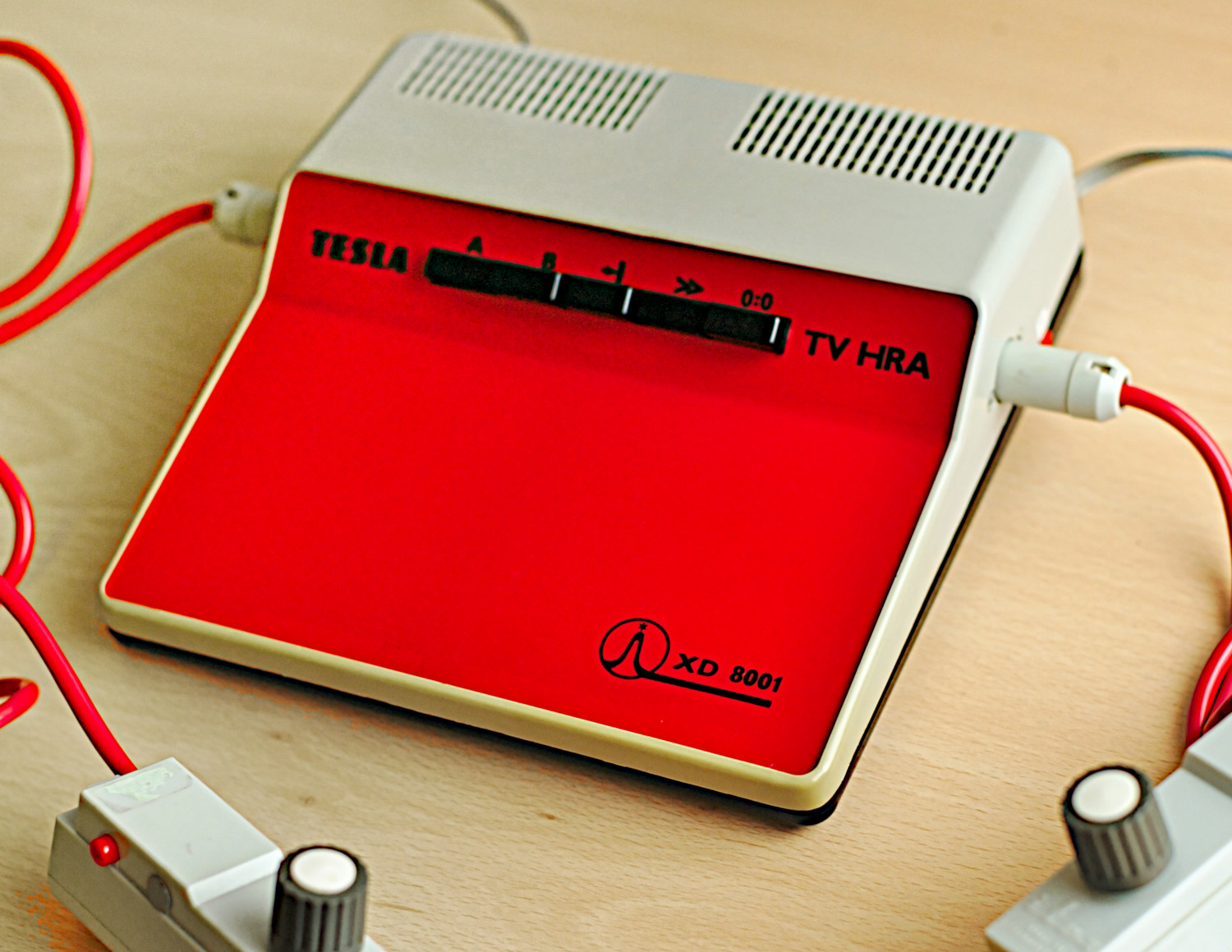 Fig. 1: The XD-8001 TV game (Photo: Herní archiv)
Game consoles in the style of the famous Pong were a phenomenon of the 1970s not only in the West: from around the turn of 1976-1977, various versions of them began to appear in what was then Czechoslovakia as well. They were usually called Television tennis, or simply Television game, and in this three-part mini-series of articles we will take a technical look at one unique specimen among them.
Game devices of this sort essentially fall into two groups: Older versions built from discrete components (or just basic TTL logic) usually offered only the most rudimentary functionality (a single game with two paddles and a ball), while being considerably complicated and expensive. More advanced models could offer a number of improvements (more game variants, boundary walls, score counting, sound) thanks to the use of specialized chips, of which, however, not many were ever created worldwide. Dominant among them is the successful AY-3-8500 (1976) by the British company General Instrument, whose competitors can however be counted on the fingers of one hand. Various clones and successors of it appeared, there were proprietary chips from several manufacturers (e.g. Atari), but it still amounts to just a handful of systems. In the countries of the Eastern Bloc, this generation of television games used almost exclusively imported AY-3-8500 chips, or their Soviet clone, the К145ИК17. This, however, does not apply to Tesla Piešťany, which was apparently the only company in the Eastern Bloc (and one of the few worldwide) to develop its own specialized chips for its XD-8001 game, designated MAS601 through 603. These were indeed sold domestically, both in the finished device and separately, yet relatively little information about them is available to this day.
I personally count myself among the curious in whom the terse information provided by period Tesla catalogs has been raising unanswered questions for years. In recent years, a certain wave of interest in the history of games can be observed worldwide, both at the general and the technical (and even academic) level; projects are emerging to document or outright emulate various systems and chips, such as the already mentioned AY-3-8500 and its successors or period microprocessors and chips from game consoles and microcomputers, and in some places even modern replicas of historically existing or even merely planned devices are being built - whether for nostalgic reasons, for historical documentation, or simply to replace gradually failing old technology. I too found inspiration in this, and decided, for similarly curious minds, and perhaps also as a showcase of domestic 1970s technology, to lift the veil of secrecy surrounding the aforementioned television games from Piešťany a little.
I should also mention that these articles could only come into being thanks to the activities of the Herní historie (Game history) association, the photographic documentation of the chips taken by Sean Riddle, and last but not least the archival materials and other information provided to the association by the author of the Piešťany chips himself, Ing. Vladimír Áč.
The history of how the Piešťany games came about somewhat exceeds the scope of this article, and is also the subject of further research; nevertheless, the chips themselves were created as early as 1977. The originally unofficial project eventually resulted in the production of both the chips and the final device, which, like the two preceding models, was designed by Ing. Ján Hladík. Production, however, only got under way after two long years, in 1979.
The XD-8001 offers four mutually similar games, as shown by the pictures known from period Tesla catalogs (Fig. 2): There is the classic television Tennis for two players, who control their paddles with potentiometers, and a Practice tennis variant for a single player, who plays against a wall. The third option is Football, with partial boundary walls that delimit the goals at the ends of the field, and with two paddles for each player (a goalkeeper and a forward on the opponent's half of the field); this game, however, resembles more hockey, because the ball (or puck) bounces off the walls back onto the field. The last game is Pelota, which is similar to Practice tennis - again a single-player game against a wall, this time however without the center net. The game also continuously counts and displays both players' scores, up to 15 points. Buttons allow switching between two ball speeds, and between manual and automatic serve.
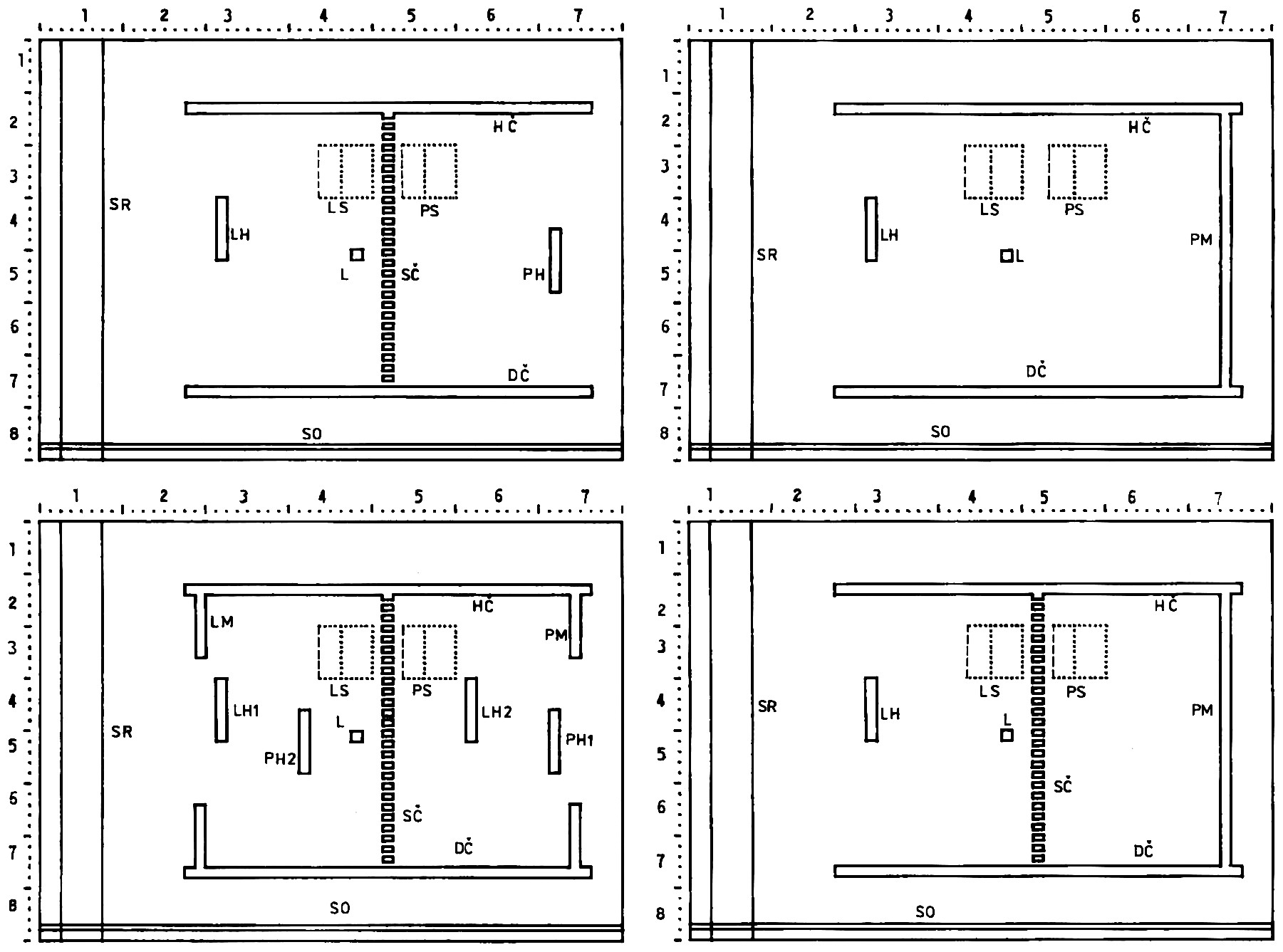 Fig. 2: The four games of the XD-8001 console (Tesla catalog)
If we compare the game with the most widespread foreign version, i.e. the aforementioned AY-3-8500 chip, it may seem very similar at first glance. On closer inspection, however, we find a number of differences. Instead of Pelota, the Western version has a Squash game, where both players play on the same side of the field; it can hide the second score in single-player games; and there are additionally two light gun games. The XD-8001, on the other hand, makes a bigger distinction between the Tennis and Football games. In football, the ball's rebounds off the players always aim toward the center of the field (from the upper half downward and vice versa), while in the other games they are random, which creates a moment of surprise. With the AY, by contrast, the ball's rebound depends on which part of the paddle it bounced off (something that would not have been feasible with the design of the domestic version). In both versions, the ball's flight angle can also change when it passes through a paddle from the back side (in which case it does not bounce). Another difference occurs after a goal, when in the Piešťany version the football starts with a kick-off from roughly the center of the field, and only in the other games is the ball served classically from the baseline. The direction of the ball also differs: with the AY it flies again in the same direction in which the goal was scored, while the XD-8001 sends the ball back away from the conceded goal - in the case of football this is more realistic, while neither of the two chips respects the relatively complex logic of tennis serves. The automatic serve is tied to two bounces of the ball off the top or bottom wall, which, besides a certain delay, also produces a practically diagonal kick-off from the corner or the center of the field, whereas with the AY the ball simply flies through the edge to the opposite side of the screen. Another significant difference is the function of the center net or line, which in the case of the AY is purely aesthetic, with no influence on the ball's movement, whereas in our version, in both tennis variants, the ball's direction may change with a certain probability when passing through this net. In football, on the other hand, it is here too just a center line that does not affect the ball (Pelota has no center line at all). While the AY can change the speed and rebound angle of the ball, as well as the paddle length of both players, the Piešťany version is fitted only with a two-speed switch (it must be noted, though, that the other parameters mentioned could also have been varied continuously with a suitable modification of the circuit, and the speed of the players' movement could have been limited as well). Last but not least, the domestic version has a true end of game: after reaching 15 points, the final score is displayed on an otherwise blank screen, whereas with the AY-3-8500, essentially just the paddles and the score counting stop working, without anything else about the game changing.
Other differences are rather aesthetic. Probably the most visible one is that the against-the-wall games are played facing right (with the AY it is the other way around), and also the score display, which in the Piešťany version appears only after a goal is scored, and then goes out with a certain delay after the game restarts. In this (and other respects) the game somewhat resembles the version published earlier in the Amatérské Radio magazine, but this is mainly related to the logic of serving and score counting. The lines along the edges of the field also differ; unlike the AY they are thick and unbroken, with characteristic overhangs on the left and right sides (where an invisible "goal line" is in fact part of the pattern), and the center net differs as well (from the AY version). The sound effects are practically the same, except that the AY indicates scored goals with a beep, while in the case of the MAS601 the whistle, apparently originally intended, did not make it into the final version. While waiting for the game to restart after a goal, you can hear the ball bouncing between the top and bottom edges of the field, even though the ball is off screen.
Let us now briefly recall the principle of this generation of television games. Today we are used to computer systems that compose practically any image as a bitmap in a certain part of memory, which is then projected onto the screen by the appropriate hardware. Due to their limited technical means, however, the game consoles of the 1970s generally did not use this abstraction, and tied the game's principle directly to the creation of the analog video signal. The analog television sets common at the time drew the picture in pixel rows (the way one reads a page of text), where the brightness of each spot was determined in real time by the voltage of the input signal. Added pulses of opposite polarity mark the beginnings of individual lines and frames - and that is essentially everything a simple console needed. It is thus just a black-and-white picture without interlaced fields, sound, or other extras. The individual game elements (paddles, ball, walls, etc.) were created by hard-wired logic in the form of suitably timed pulses, synchronous with the drawing of the picture on the TV. In the simplest version, a few monostable flip-flops sufficed: as the TV gradually draws the picture from top to bottom, a capacitor charges up and, depending on the position of the potentiometer in the controller, sooner or later reaches the decisive voltage threshold. This produces a pulse that draws a bright patch on the screen - a paddle, for example. Merging the pulses of the various game elements directly yields a finished video signal for the TV, while comparing their coincidence in time detects collisions: if the TV is supposed to draw the picture of the ball and a paddle at the same time, it is clear that we have hit it and the ball should bounce (the flip-flop controlling the ball's direction toggles). Such a hard-wired principle is admittedly quite limiting and inflexible as far as the game's functionality goes, but it works even with very modest technology, without any pixels or bytes of memory.
Thanks to this, the oldest console, the Magnavox Odyssey, and its clones made do with a modest number of discrete transistors, but many later systems adopted the same principle as well. For foreign manufacturers, not even the arrival of microprocessors brought a fundamental change; at first they merely replaced the game's control logic, while the video signal continued to be created in real time by combining the partial signals of the individual game components, more or less improved. This is how the microcontroller-driven MOS7600 game chip does it, and a nice example is also the company Atari, where a comparable principle persisted from the first Pong, through the microprocessor-controlled Atari 2600 console, all the way to the XL/XE computer line in the 1980s (these still even have collision detection and reading of potentiometer and light gun positions, although they also adopted a number of features from larger computers). While in our country we apparently have no example of a similar intermediate step between a television game and a computer, the Piešťany television games naturally used the principle described above. At the time of their creation, it was the usual, and actually the only usable option.
Let us now take a look at the innards of the Tesla XD-8001 console. After unscrewing the case, our colleagues from the Herní historie association were presented with a board populated with period components (Fig. 3), including the trio of MAS601-603 circuits. In the following pictures, I redrew the board and converted it into a detailed schematic, exactly as the game was actually manufactured by Tesla. Unlike the relatively well-known catalog circuit of the MAS chips, here we see the truly complete device, but we also find further differences (I list them in brackets and will return to them later). The schematic shows a stabilized -18V power supply, a simple sound circuit with a small speaker directly in the device, and at the bottom the controllers, connected via the then-common DIN connectors, and the buttons for setting up the game. The very modest decoupling of the supply voltage by just a single electrolytic capacitor is surprising (not very effective at higher frequencies and, judging by its numbering, possibly even added only as an afterthought).
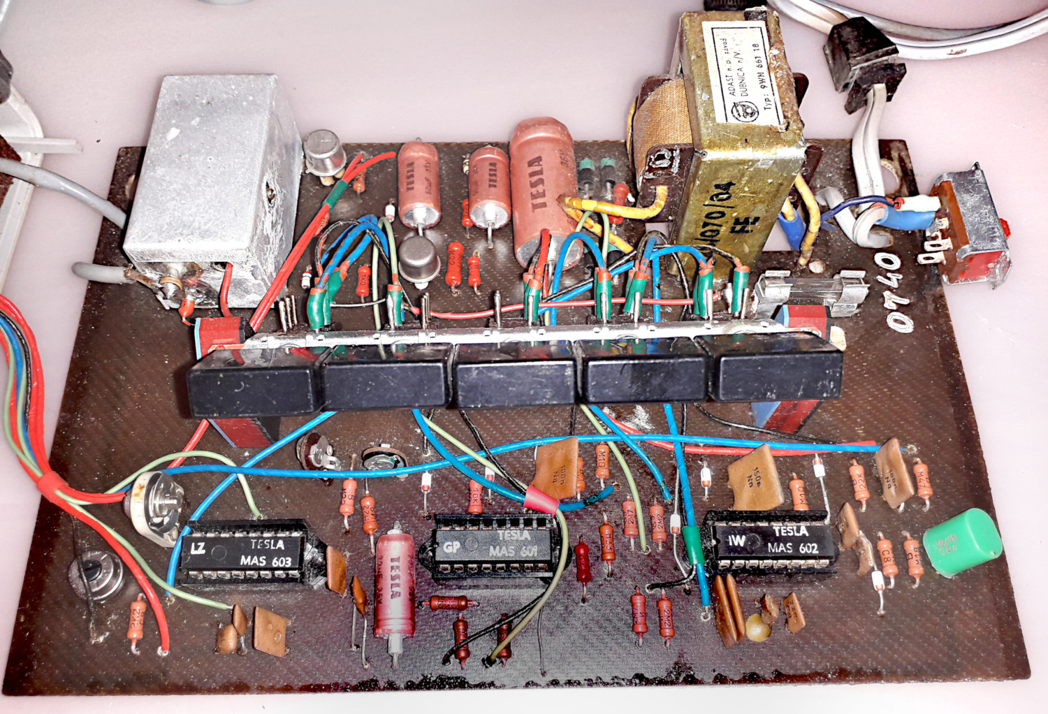 Fig. 3: The board in the XD-8001 (Photo: Herní archiv)
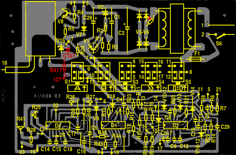 Fig. 4: Component layout on the board
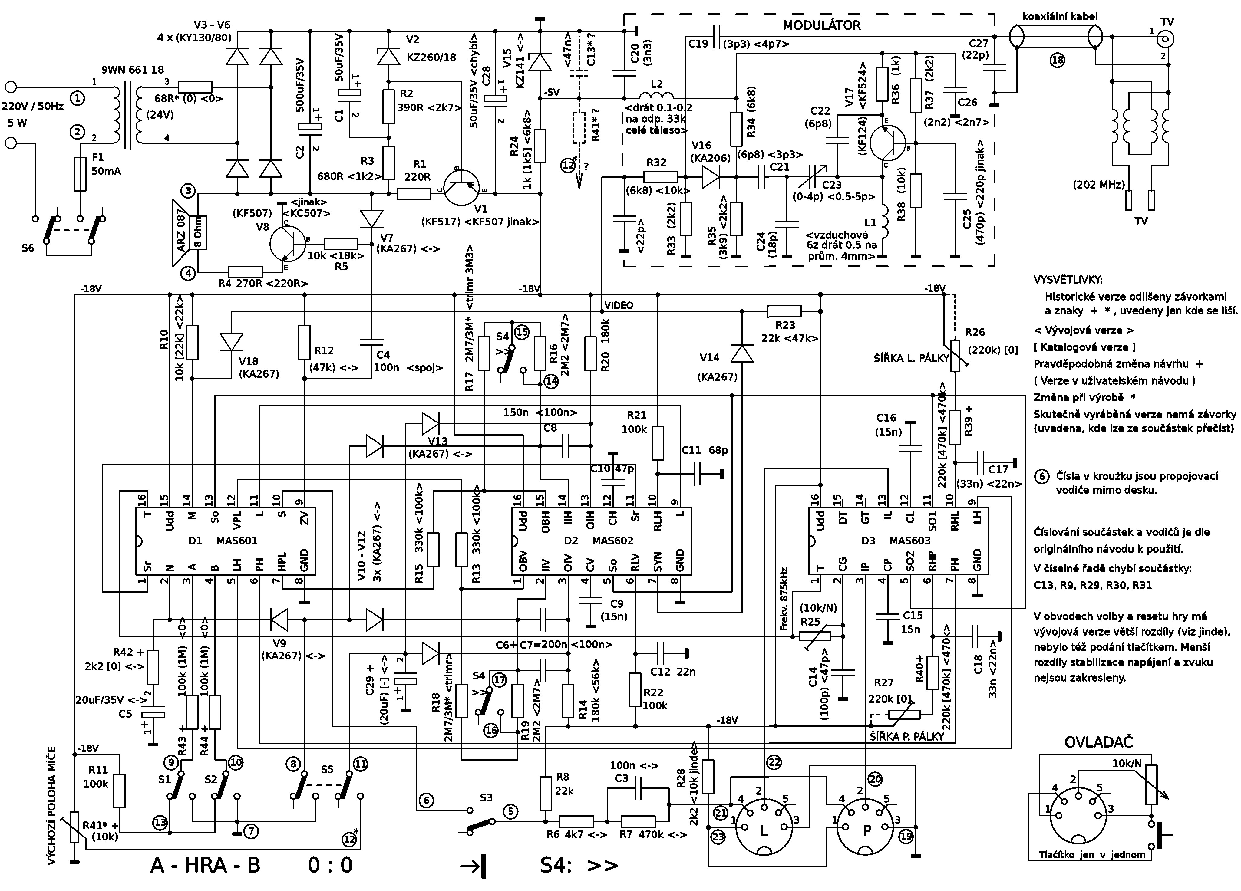 Fig. 5: Detailed schematic of the XD-8001 across development versions
The schematic further reveals the modulator for the output to the television, in reality hidden in a small metal box. In one of my earlier articles I commented on how the construction guides published in period magazines explained this part of the circuit rather poorly, treating it as something more or less obvious given the then still strong amateur radio tradition, so I will try not to repeat the same mistake and shed some light on the circuit's function. Analog television broadcasting encodes the video signal in probably the simplest possible way, which is amplitude modulation: a high-frequency signal (a.k.a. the carrier wave) changes its amplitude (in practice, its voltage) depending on the transmitted content. The right-hand part of the circuit (with a transistor in a common-base configuration) is thus essentially an oscillator producing that high-frequency waveform. The modulation is handled by diode V16, which feeds the sine wave into a common node with the transmitted video signal - inevitably, however, it only pushes through the part of the waveform whose voltage is lower than the current state of the signal, which is precisely what produces the desired change of amplitude according to the transmitted content. Capacitor C19 then passes only the varying high-frequency part to the output, which, in a circuit this simple, will not be of any particular quality (cutting off part of the waveform does not make for a nice sine wave), but the television will understand it, and any sins remain hidden inside that little metal box and the shielded cable. Very similar circuits can in fact be found in most period television game construction guides (in the case of the recommended circuit for the Western AY-3-8500, though, with the face-saving note that the circuit is intended only for testing in a laboratory).
The output cable is fitted with a rather unusually arranged combination of two different connectors, because at the time, the first TV sets with a 75Ω coaxial antenna connector were only just coming onto the market, while older sets still used flat symmetric 300Ω connectors. An adapter intended for connecting older cables to newer TVs is used here essentially in reverse, as a coaxial connector and at the same time a branch, via a short cable, to the older flat version.
The core of the game itself is the MAS601 circuit, driven by an 875kHz clock frequency fed from the MAS603 into the T input. The MAS601 creates both the horizontal and vertical sync pulses (SR and SO outputs), and puts together the complete picture and sound of the game (M and ZV outputs). By itself, however, it only generates the immobile shapes digitally (using various counters), that is the walls, the center net, and the score. The remaining two circuits cooperate in creating the moving parts of the game, and unlike the MAS601, they use the analog principle common in older consoles. The MAS603 handles both paddles, whose position is controlled by the voltage from the controllers on the IL/IP inputs. According to its magnitude, in each frame a pulse is created on the LH/PH outputs, at the required offset from the vertical sync pulse (SO1/SO2 inputs), using the capacitors on the CL/CP and RHL/RHP pins. This pulse is then fed into the MAS601, where it delimits the displayed paddle in the vertical direction.
The MAS602 circuit takes care of both the position and the display of the ball. The direction of movement is controlled by the HPL/VPL outputs from the MAS601, whose signal (after magnitude limiting by means of the OBH/OBV pins and adjustable resistors) slowly charges or discharges the capacitor between the IIH/OIH and IIV/OIV pins, respectively — these are essentially analog integrators, whose output voltage then controls the position of the displayed ball in the same way as with the MAS603. In the case of the ball, both components (horizontal and vertical) are merged into a single output L (the designation comes from the Slovak word "lopta", meaning ball), which is practically a finished video signal of the ball. A second, invisible ball is also added, during the blanking period at the beginning of a scan line; the MAS601 circuit uses it to safely keep the ball on the field after a goal, when the visible ball is not displayed. The SYN output merges both sync pulses for the TV, which, due to their different voltage level, cannot be mixed into the video signal directly in the MAS601.
The course of the game is further controlled by the A/B/N inputs (game selection and score reset), and the serve after a goal by the rather atypical S input — at a level of -18V it holds the game stopped, while at ground level it releases the ball into play. This is done with a button on the controller, connected via a differentiating circuit that limits even a longer press to a short pulse. If, however, the S input is disconnected (by an unusually wired switch), control is taken over by the automation, connected to this input from inside the MAS601 through a resistor, and the ball is then released into play after two bounces off the top/bottom edge of the field.
Understandably, every project goes through a number of changes during its creation, and the XD-8001 game was no exception. The various versions of the printed materials, however, were not created at the same moment, so it happened that the circuit given, per the custom of the time, in the user manual does not fully match the version printed in the component catalog, and in places not even the actually manufactured devices. This gives us an interesting insight into the genesis of the whole device and reveals which of its parts changed. I tried to capture the smaller deviations in the redrawn schematic using different kinds of brackets, but there are also bigger changes, which can best be illustrated on the circuit for resetting the game to its initial state.
In the upper left part of Figure 6 we see a still relatively simple version, as it was attached to the development documentation of the MAS60x chips themselves. Here, one contact of the reset button clears the score, while the other merely moves the ball to the right for the duration of the press, most likely so that on first power-up it would safely get from the edge onto the field. A more specific initial position of the ball was not addressed here at all, although the early version of the MAS601 circuit itself blocked unwanted goals at the start of the game, until the ball first crossed the center line. Different values of other components suggest a somewhat faster ball movement, and the reduced voltage on the game-selection inputs is also peculiar. This version also did not provide for a manual serve using the button in the controller (outside the frame of the picture).
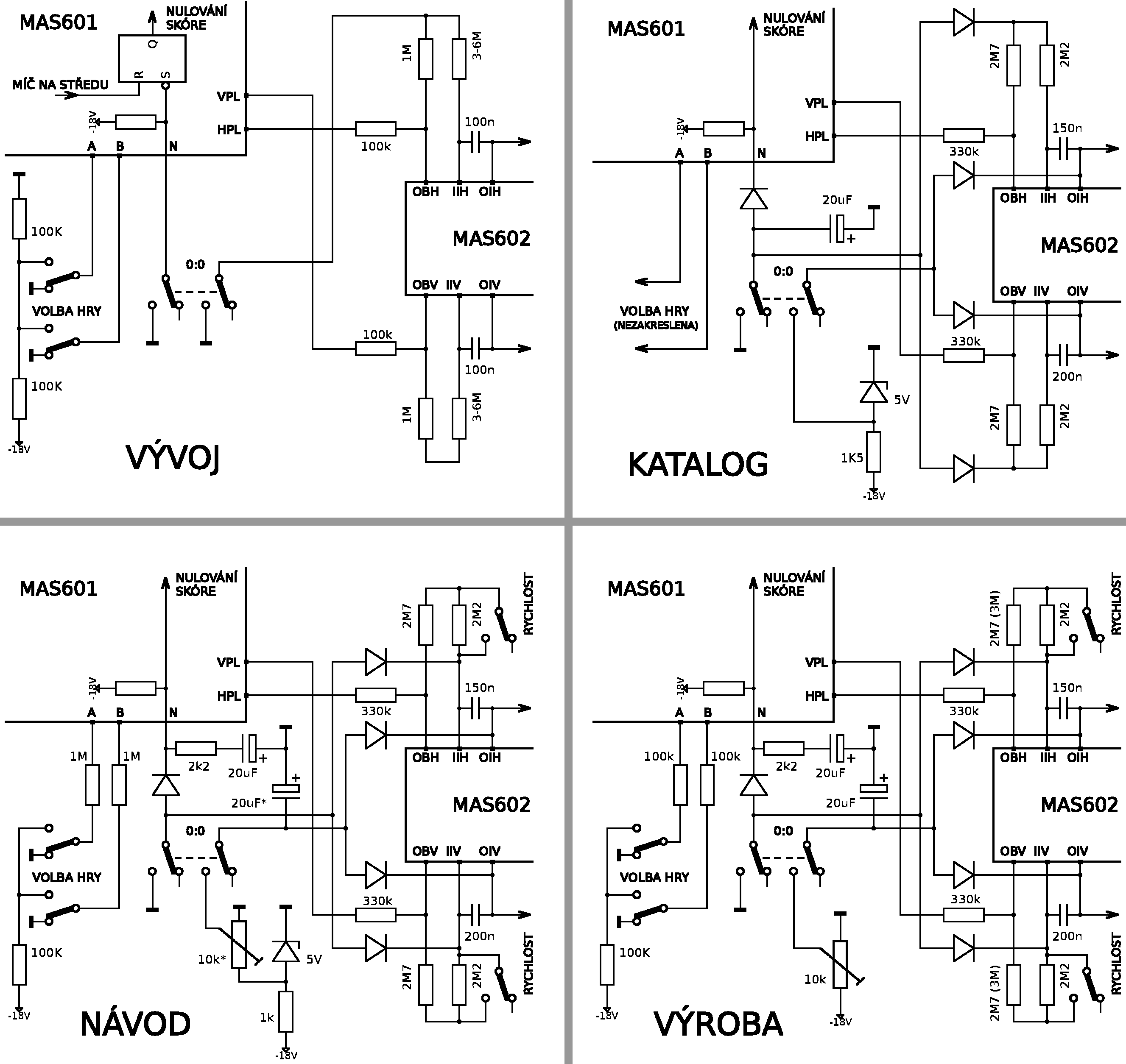 Fig. 6: Comparison of the game-start circuits
The version printed in the component catalog (top right) no longer relies on the game's initial insensitivity to unwanted goals, which had apparently been dropped in the meantime. A sufficient duration of the reset signal is ensured here by an additional capacitor, slowly charged through a pull-up built into the MAS601. The signal, branched through diodes, also closes the ball-position integrators (this time both of them), whose capacitors are moreover charged through further diodes to a predetermined voltage from an auxiliary source, so that the ball's movement always starts roughly from the center of the field. This makes for a nicer, and also safer, start of the game from the user's perspective.
If we look into the XD-8001 user manual (bottom left), we see a more forceful action on the integrators, and also noticeably greater caution in handling the inputs of the MAS601 circuit, where series resistors were added (reminiscent rather of the way bipolar circuits are handled, debatable for MOS circuits); this caution is also laid bare by the use of the then relatively expensive sockets. A second capacitor also extends the setting of the ball's initial position, which is now adjusted with a trimmer - while this was printed in the manual, the manufactured printed circuit boards still provided only for a series resistor in the trimmer's place, and the added capacitor, too, with its different type and high number, looks as if it did not originally belong on the board. Switches for selecting the ball speed also appeared. Even then further changes followed, because in the actual device (bottom right), the trimmer for the ball's initial position is mounted outside the originally intended board layout in such a way that it does not use the auxiliary -5V source at all. The somewhat overshot series resistors in the game-selection inputs were also reduced, and the faster ball movement was slowed down somewhat during production by increasing two resistors.
Further changes would be found in the assortment of adjustment trimmers and other details, or in the power supply, which was significantly different in the oldest version and, given the somewhat overdimensioned output voltage of the transformer, apparently also struggled with overheating - on the board we find two limiting series resistors, one of which was mounted additionally, outside the intended board layout. Then again, obtaining a suitable transformer at the time was probably no easy matter. Likewise, it proved impossible to secure a dedicated case for the device, so it was eventually designed into a housing taken over from the production of desktop calculators at Tesla Bratislava; the controller housings come from toy remote controls; and, for example, ready-made coils were practically unavailable at the time, so instead of inductance values, the documentation rather contains instructions for winding them by hand, which was common back then.
So much for a brief look at the transformations of the device, which left their imprint in the period documentation. It was by no means a bad device in its day; it is just a pity that, like a number of other Czechoslovak products, it arrived several years behind the global trend, and sold for what was then an unpleasantly high price (1,610 Kčs).
In closing, I admit that a number of further questions remain: Why the division into 3 circuits? Why the -18V voltage? Why is half of the game essentially analog? How does the game logic actually work? These and other questions I will save for the next two articles, in which I will try to dive even deeper - directly into the internal structure of the MAS601-603 integrated circuits.
Sources:
- Photo documentation of the XD-8001 (Herní archiv)
- Scan of the printed circuit board
- Set of integrated circuits for the construction of television games MAS601, MAS602, MAS603 (Technical reports, Tesla Rožnov, 1979)
- Televízna hra XD 8001 - user manual (Tesla Rožnov, n.p., Piešťany plant, probably 1979)
- Ing. Vladimír Áč: Interview for the Herní historie association (2025)
- Ing. Vladimír Áč: Technical documentation of the MAS600/601-603 (unpublished working version, c. 1977-1978)
- AY-3-8500 datasheet (General Instrument)
- Pong Story
- Video recording of the game
Image sources:
- 1. Picture of the Tesla XD 8001 by Herní archiv
- 2. Tesla catalog (the same pictures also appear in the Technical report and the development documentation)
- 3. Photo documentation provided by Herní archiv
- 4-6. My own drawings (using the scan of the printed circuit board that you can find here)
Tesla XD-8001 television game
- The Tesla XD-8001 television game under the microscope
- Obvody MAS601-603 pro televizní hry pod mikroskopem
- Obvody MAS601 vs AY-3-8500 pod detektivní lupou